Powering Racecars

My first design role on the FSAE project team was focused on supporting components for the drivetrain system, such as mounts and spacers for sprockets, as well as a motor shaft. The following year, I decided to take on a more electrically focused role and worked on the Power Distribution Unit (PDU). This board was focused on routing regulated power to the correct systems across different states of the car. The main size and weight contributors are the high ampacity mechanical relays which route power to non-critical systems. Additionally, there is fusing to all power outputs as well as timing logic for an LED indicator mounted at the top of the car to indicate whether high voltages are present, a normal condition that warns observers to keep their distance to avoid danger. For more details, see my semester technical report below.
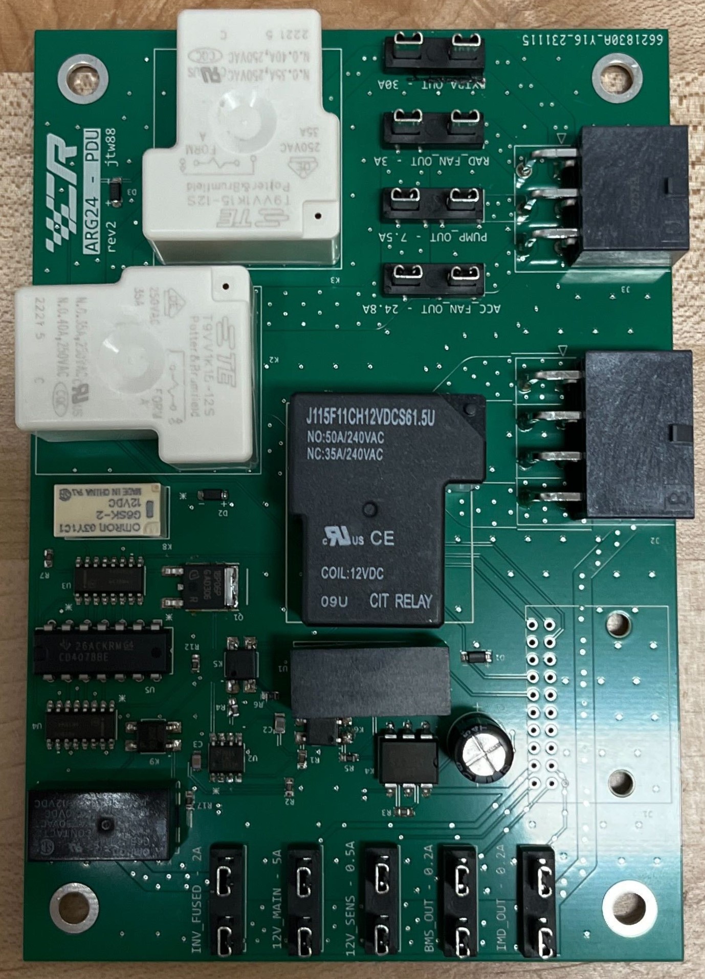
Second Manufactured PDU Board

Designing Radios

During my junior fall, I worked with two other electrical engineering students to design a radar transceiver in a generic 45nm process with minimal power, area, and crosstalk. The goal of the transceiver was to implement an FMCW radar operating between 25 and 30 GHz with minimized crosstalk by using a full duplex transceiver with a delay line between the power amplifier and LNA to cancel radiation directly from the transmitter antenna to the receiver antenna, as the desired signal at the would be the scattered signal from a target.

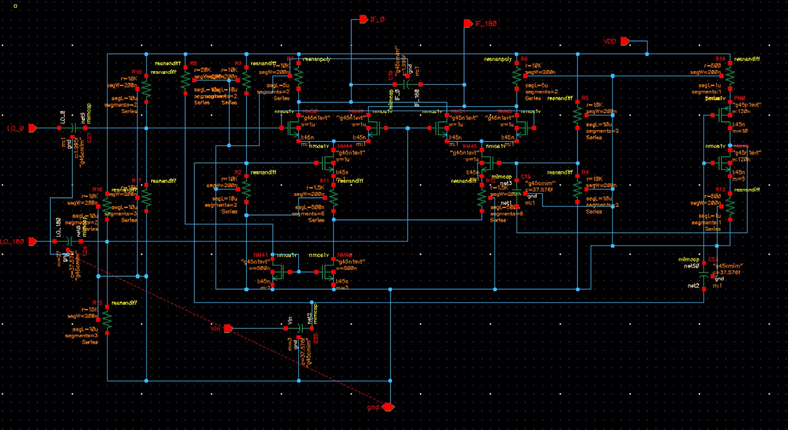
This was our first introduction to mixers, power amplifiers, and LNAs as the semester had focused on becoming familiar with understanding how to analyze complex transistor circuits and learning the fundamentals, such as gain, bandwidth, biasing, manufacturing restrictions, noise, and feedback. Applying what we had learned was a challenging task and to do so, we divided the work into three, each person having ownership of one role. This allowed one of us to dive deep into the complexities of our circuit and bounce ideas off of each other to learn more about each other's circuits and develop creative solutions. I had ownership over the mixer, which ended up being a double-balanced differential active mixer. Some difficulties with the mixer included long transient simulation times, a single to differential ended converter being needed for the local-oscillator, and power amplifier having difficulties driving the mixer.

Mixer Schematic

Characterizing Silicon

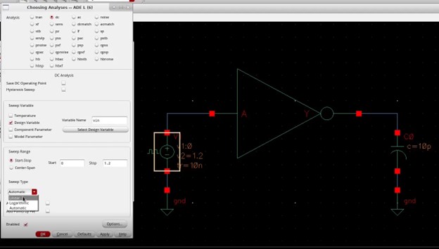
Through multiple classes at Cornell, I have become familiar with the integrated circuit design tool, Cadence Virtuoso. Within my classes, I have developed decoders, D flip flops, low-noise low-frequency neural amplifiers, biquad filters, and digital to analog converters. A core building block of many of these devices is the inverter, a useful piece of both analog and digital circuitry. Within my Digital VLSI class, we were tasked with characterizing an inverter for later projects in that class to ensure that we were comfortable using Cadence and could have a reference for future design projects. This project (video report shown below) walks through the schematic, layout, and simulation for an inverter on its own and in an FO4 setup.

Inverter Simulations

Beamforming Arrays

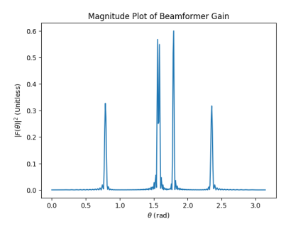
As part of a class covering RADAR technology, I developed a term paper covering antenna beamforming and digital processing for target locking with applications in continuously evolving time domain systems for target detection and tracking. This work combines data science and basic optimization algorithms with antenna signal processing for use in mixed signal radios with DSP. The applications for this work are mainly in vehicle telemetry and control.

90 Element Beamformer Response

Powering Racecars II

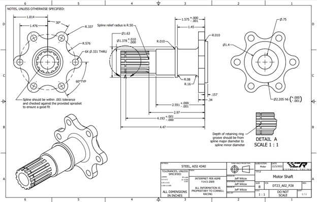
When I first joined the FSAE project team, I wanted to be a mechanical engineer so I got machine shop certified and worked on developing my mechanical design tools. Coming from an FRC robotics team, I was familiar with Solidworks but the team used Autodesk Inventor, a slightly different tool that was easy to get the hang of once I understood how the actions from Solidworks mapped into the Autodesk actions. The mechanical design was geometrically focused, with more attention to load cases relating to the driven sprocket and motor shaft. Working in this design role introduced me to developing part drawings and mechanical tolerancing, as well as communicating design changes within a team.

Motor Shaft Drawing

Enabling Biosensors

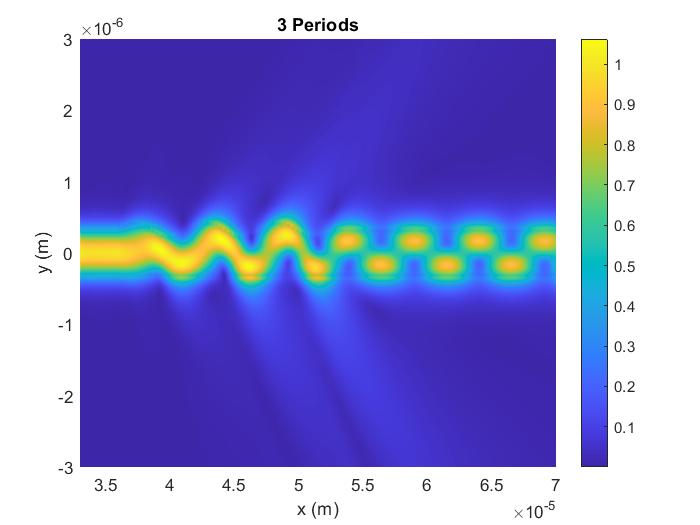
During my sophomore spring, I took a course on photonics and THz frequency electromagnetics which covered dielectric waveguides, free space propagation, perturbation theory, and acousto-optical effects. As a final project, I worked with two students in the Masters of Engineering program to design a mode coupler for bio-sensing applications. The project involved hand calculations, matlab simulation, computer aided design, and additional FDTD simulations for verification.

Mode Converter with Grating Length of 3 Wavelengths